RTTY demodulator using NJM2211
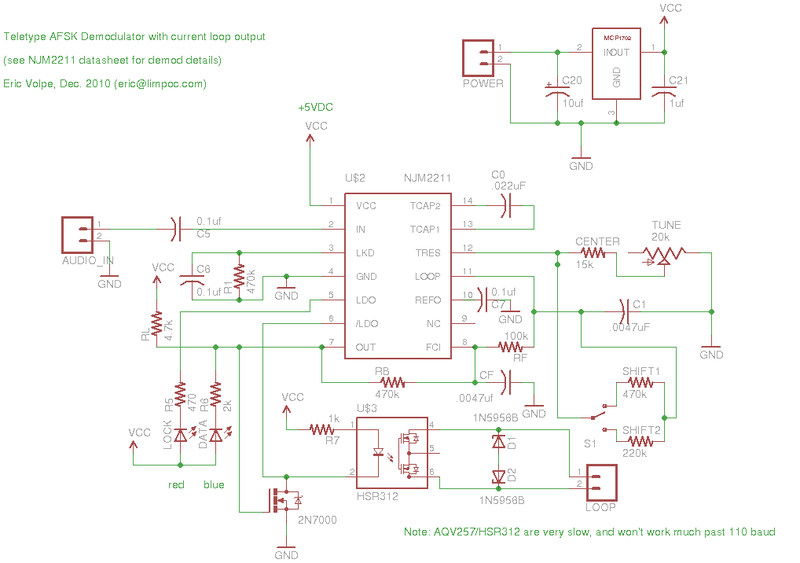
The board is a straightforward application of the NJM2211 FSK decoder chip. It accepts an audio signal and decodes it into on and off keying of a teletype current loop circuit via an optical isolator which protects your computer or radio from the high voltage and inductive spikes on the loop. It has the additional feature that when it's not locked on to a signal, it keeps the the loop closed so that the attached teletype machines won't "run open."
The board was designed to cost $20, and as such it does not include various bells and whistles such as the ability to invert mark and space. As is, it will correctly decode the ITTY signal, and if you're getting audio from a radio, it's probably a sideband receiver where you can switch to the opposite sideband, which achieves the same thing. The board does not provide the loop current – like a keyboard or tape reader, it just makes and breaks the existing circuit. The output can handle 60 or 20mA loop and is safe to 200 volts. There's been discussion on the Greenkeys mailing list about how to make a loop supply, if you need one.
George Hutchison W7TTY's excellent ITTY service can be found at http://rtty.com and is a perfect source of AFSK data for this board. In addition, there are many web-accessible software defined radios available to the public. An index of them can be found at http://websdr.org – choose one, find a signal, plug your computer's audio output into this board, and watch your machine print the traffic!
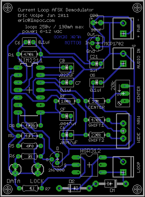
All connections (audio, power supply, and tty loop) are via small screw terminals. The board's dimensions are 1.9 by 2.6 inches. The instruction sheet shipped with the boards can be found here: instruction sheet The latest (very rough) parts list is here: BOM
- Notes.
There are a number of optocoupler / solid-state relay parts that can work here. They vary in peak load voltage, current-handling capability, switching time, and input requirements. The current winner in terms of cost/performance is the PS7141E, which costs $1.57 at quantity 10-100: Measured values from sample part: LED forward current: 11 mA w/ 330 ohm series resistor - 13mW dissipation, max = 50mW. Closed output switch drops 2v @ 60mA = 120 mW (max = 560 mW continuous) - 33 ohms, right to spec. This isn't great, but not tragic on a 150v loop. For lower on-resistance, you pay more money, or use more components. At least it drops less than an actual selector magnet, and isn't inductive. Turn on time < 500uS, turn off time 70uS.

