Difference between revisions of "Tube amplifier"
| (7 intermediate revisions by the same user not shown) | |||
| Line 1: | Line 1: | ||
| − | This is a Williamson-style push-pull audio amplifier designed around the RCA type 815 transmitting tube as the output stage. The 815 was designed during WWII as a VHF transmitting tube for use aboard aircraft, but is suitable for audio use as well. It is a dual beam-power pentode, making it convenient for push-pull use. | + | This is a Williamson-style push-pull audio amplifier designed around the RCA type 815 transmitting tube as the output stage. The 815 was designed during WWII as a VHF transmitting tube for use aboard aircraft, but is suitable for audio use as well. It is a dual beam-power pentode, making it convenient for push-pull use, however the cathodes and screen grids of each pentode are connected together internally, so it's not as flexible as it could be. |
I ran across a pair of 815s in a surplus shop and thought it would be fun to learn a little about vacuum tube electronics and design an audio amplifier around them, partly because they are an obscure part without an audiophile cult following and thus cheap, and partly because they look like little robots with their two plate caps. | I ran across a pair of 815s in a surplus shop and thought it would be fun to learn a little about vacuum tube electronics and design an audio amplifier around them, partly because they are an obscure part without an audiophile cult following and thus cheap, and partly because they look like little robots with their two plate caps. | ||
| − | There aren't any (solid state) semiconductors in the signal path, but for convenience I used silicon rectifiers for the plate supply and modern semiconductor voltage regulators for the screen and bias supplies. Plate voltage is around 450V, screen voltage around 200V, and grid bias around -20V. Plate current with no input is around 14mA per pentode. Audio power output before distortion starts is around 15W (per channel) at 1KHz. It's plenty loud. | + | There aren't any (solid state) semiconductors in the signal path, but for convenience I used silicon rectifiers for the plate supply and modern semiconductor voltage regulators for the screen and bias supplies. Plate voltage is around 450V, screen voltage around 200V, and grid bias around -20V. The screen grid, which is shared between both pentodes, needs a stiff power supply. Plate current with no input is around 14mA per pentode. Audio power output before distortion starts is around 15W (per channel) at 1KHz. It's plenty loud. |
| − | + | Not shown in the schematic is the AVR microcontroller based remote control and power sequencing board. It has an infrared remote receiver, digital volume control (the only silicon in the signal path :) and handles sequencing on power up/down: on power up, it starts the bias and filament supplies first, waits until the tubes are fully heated, then starts the screen and plate supplies, while muting the input. On power down, it mutes the input, then shuts off the screen and plate first, waits for the HV supply to leak down, then shuts off the filaments and bias supply last. | |
| + | <p> | ||
| + | Future modifications will involve digitally instrumenting various operating parameters like plate current, screen current, bias, and output power level. | ||
[[File:815.png|800px]] | [[File:815.png|800px]] | ||
| + | |||
| + | </p> | ||
| + | |||
| + | There's even a PC board version (minus the power supplies and the output tube): | ||
| + | <p> | ||
| + | |||
| + | [[File:815board.png|400px]] | ||
| + | </p> | ||
[[Category:Electronics]] | [[Category:Electronics]] | ||
Latest revision as of 08:47, 27 November 2013
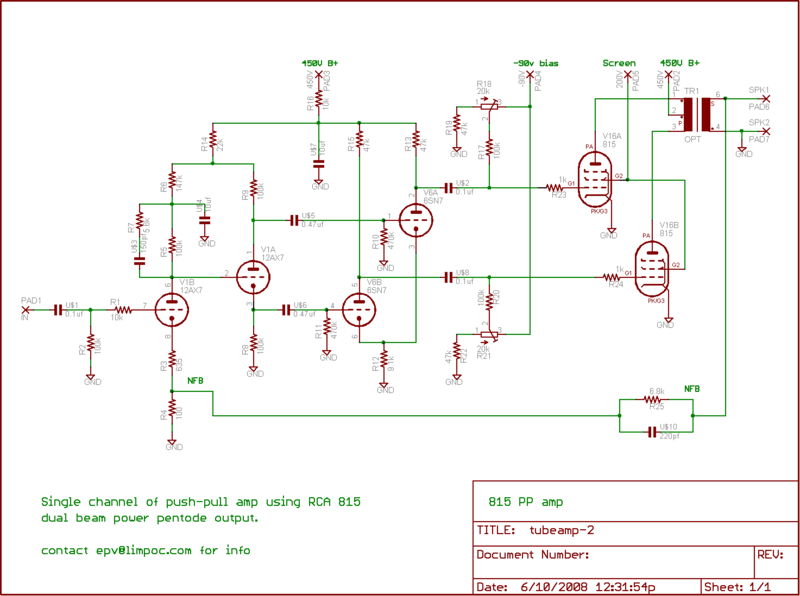
This is a Williamson-style push-pull audio amplifier designed around the RCA type 815 transmitting tube as the output stage. The 815 was designed during WWII as a VHF transmitting tube for use aboard aircraft, but is suitable for audio use as well. It is a dual beam-power pentode, making it convenient for push-pull use, however the cathodes and screen grids of each pentode are connected together internally, so it's not as flexible as it could be.
I ran across a pair of 815s in a surplus shop and thought it would be fun to learn a little about vacuum tube electronics and design an audio amplifier around them, partly because they are an obscure part without an audiophile cult following and thus cheap, and partly because they look like little robots with their two plate caps.
There aren't any (solid state) semiconductors in the signal path, but for convenience I used silicon rectifiers for the plate supply and modern semiconductor voltage regulators for the screen and bias supplies. Plate voltage is around 450V, screen voltage around 200V, and grid bias around -20V. The screen grid, which is shared between both pentodes, needs a stiff power supply. Plate current with no input is around 14mA per pentode. Audio power output before distortion starts is around 15W (per channel) at 1KHz. It's plenty loud.
Not shown in the schematic is the AVR microcontroller based remote control and power sequencing board. It has an infrared remote receiver, digital volume control (the only silicon in the signal path :) and handles sequencing on power up/down: on power up, it starts the bias and filament supplies first, waits until the tubes are fully heated, then starts the screen and plate supplies, while muting the input. On power down, it mutes the input, then shuts off the screen and plate first, waits for the HV supply to leak down, then shuts off the filaments and bias supply last.
Future modifications will involve digitally instrumenting various operating parameters like plate current, screen current, bias, and output power level.

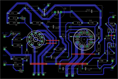
There's even a PC board version (minus the power supplies and the output tube):
