Difference between revisions of "Solar power instrumentation"
| Line 13: | Line 13: | ||
This gives graphs as shown below, with excursions above and below the zero line reflecting cycles of charging and discharging of the batteries. | This gives graphs as shown below, with excursions above and below the zero line reflecting cycles of charging and discharging of the batteries. | ||
| − | [[Image: | + | [[Image:solar.png|700px]] |
[[Category:Electronics]] | [[Category:Electronics]] | ||
Revision as of 05:23, 17 January 2012
480 watts of panels on roof (mfgr rated 2x85W, 2x95W, 2x60W) wired 2x in series, 3x in parallel, for around 30vdc under load. Charge controller is a switcher that steps the 30v down to 12v nominal to charge bank of batteries, wired 4x in parallel for ~440 AH (~5 KWh). Peak current into batteries is about 17 amps. inverter and dc loads draw from battery. There is a big brass 0.0001 ohm calibrated shunt resistor in the negative leg of the battery circuit, giving 100uV drop per amp flowing through the shunt. A monitor measures the shunt current as well as the battery voltage periodically and transmits the data via RF to whomever's listening. The data from the receiver gets logged and graphed sometimes.
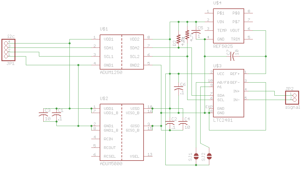
The tiny signal from the shunt resistor is read directly by an electrically isolated A/D converter module. The module uses a LTC2481 16-bit bipolar A/D converter from Linear which can read the microvolt-level input directly, and speaks i2c. The module also supplies isolated DC power to the converter and an i2c isolator (ADUM5000 and ADUM1250, both from Analog Devices) and connects to the CPU by a four-wire connection (+v, gnd, sda, scl). This way the input can go positive (when net current flow into the batteries is positive) and negative (during discharge.)
One of the onboard A/D converter inputs of the CPU itself is used to measure the always-positive battery voltage through a voltage divider that divides the nominally 12v power down into the ADC's input range, so that we can see voltage and current simultaneously. The onboard ADC is only 10 bits wide and noisier than the external LTC2481 but it's good enough for battery voltage, which has a much smaller dynamic range.
The CPU talks to the A/D module and controls a packaged RF data module, waking it up from sleep mode only when there is data to transmit.
This gives graphs as shown below, with excursions above and below the zero line reflecting cycles of charging and discharging of the batteries.
